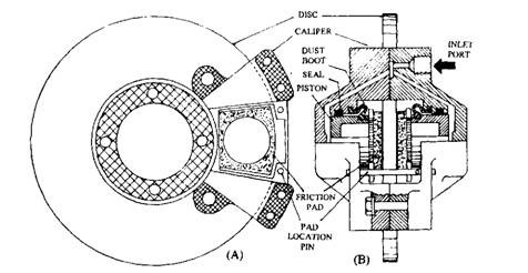
Posts

disc brake caliper

Image
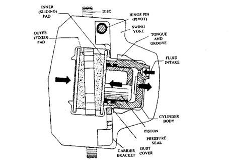
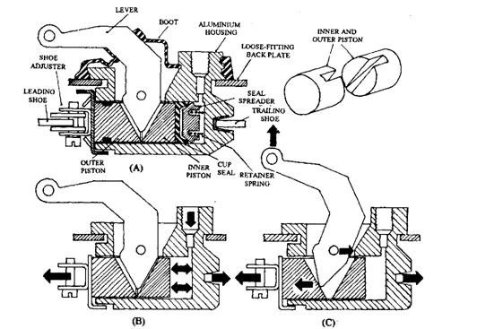
Disc Brake Pad Support Arrangements Swing Yoke Type Brake Caliper This disc brake caliper is a single cylinder unit and is of light weight. The caliper unit uses a rigid yoke of steel pressing, a cylinder assembly, two pads and a carrier bracket bolted to the suspension hub carrier. A tongue and groove joint rigidly secure the cylinder to one side of the yoke frame while the yoke itself pivots at one end on it supporting carrier bracket. The disc is mounted on the transmission drive shaft hub which it is mounted provides the drive to the disc. The lining pads are supported on either side of the disc in the yoke frame (Fig. 28.28). Fig. 28.28. Swing yoke type brake caliper During operation of the foot brake, hydraulic pressure pushes the piston and inboard pad against their adjacent disc face. At the same time, the hydraulic reaction moves the cylinder in the opposite direction so that the outboard pad and cylinder body are bridged. Then the yoke pivots, forcing the outboard pad against

Disc Brake Layouts

Image
Disc-brake Assembly A disc-brake has a rotating cast-ion disc, bolted to the wheel hub and a stationary caliper unit. The caliper straddles the disc and is bolted to the stub-axle or swivel-post flange. It is made of cast iron in two halves (Fig. 28.25) and each half forms a separate cylinder block with the cylinder axis perpendicular to the disc. The two cylinders are connected together by drillings at the pressure faces of the two caliper halves near to the inlet port (Fig. 28.25B). A bleed-screw drilling also intersects at this junction Fig. 28.25. Double-piston-caliper disc brake Each cylinder uses a rubber sealing in the form of a ring located in a groove in the body and a hollow piston protected by a dust-cover. A friction pad in the form of a segment is bonded to a steel plate and is sandwiched between each piston and the disc face. These pads fit into slots formed in each half of the caliper housing and are held in position by retaining pins, or spring plates. The application o

Disc Brake Cooling

Disc Brake Cooling The cooling of the brake disc and its pads takes place mostly by air convection, however wheel hubs also conducts away some of the heat. The rubbing surface between the rotating disc and the stationary pads is exposed to the frontal air stream of the vehicle and hence to the directed air circulation. Therefore, under continued brake application the disc brake is consid­erably more stable than the drum brake. Also, the high conformity of the pad and disc, and the uniform pressure allows the disc to withstand higher temperatures compared to the drum brake. Since far less distortion takes place in discs compared to drums, the disc can operate at higher temperatures. Also, the disc expands towards the pads, whereas the drum expands away from the shoe linings. Consequently, in the hot condition the disc brake reduces its pedal movement, but the drum brake increases its pedal movement. The discs are made of cast iron and are ventilated to considerably improve the cooling

Friction Lining and Pad Materials

Image
Properties of Friction Lining and Pad Materials Friction Level The coefficient of friction should be sufficiently high to limit brake pedal effort. It should not be so high that it causes grab, or in the extreme cases lock or sprag. In such a situation rotation of the drum becomes impossible. The friction material must be com­patible with the degree of self-energization (Fig. 28.32). The average coefficient of friction of modern friction materials is between 0.3 and 0.5. Resistance to Heat Fade This property allows a lining or pad material to retain its coefficient of friction with an increase in rubbing temperature of the drum and shoes or disc and pads. A decrease in the coefficient of friction requires greater brake pedal effort and results in poor braking response. The changes in the coefficient of friction as a consequence of rising working temperatures are also partly caused by the additional curing of the pad due to chemical changes in the binder resin (Fig. 28.32). A progressiv

Brake Fluid

Brake Fluid A brake fluid meets the international standards set in the United States by the Society of Automotive Engineers (SAE) and Department of Transportation Federal Motor Vehicle Safety Standard (FMVSS). The major characteristics of a brake fluid include : (a) Low viscosity. The brake fluid must flow easily over a wide temperature range and be able to operate in very cold conditions. (b) Compatibility with rubber components. Besides resisting corrosion of metal parts, it must be chemically non-reactive to the rubber seals etc. It must be non-injurious to the system. (c) Lubricating properties. It must reduce friction of moving parts, especially rubber seals. (d) Resistance to chemical ageing. It should have a long storage life and be stable when in use. (e) Compatibility with fluids. It must be compatible with other fluids of its type. if) High boiling point. Most braking systems use a glycerin-alcohol (glycol) fluid with additives to meet the required specifications. Because of

Separate Rear-wheel Parking-brake Mechanism

Image
Separate Rear-wheel Parking-brake Mechanism In this parking-brake shoe-expander, the hydraulic foot-brake cylinder body is bolted to the back-plate. A piston at each end actuates the shoes. A link-strut bridges the two shoes, one end connecting against one shoe web and the other end acting as the pivot point for the parking-brake lever attached to the other shoe. Two alternative lever layouts are presented in Fig. 28.44. It is perpendicular to the shoe in Fig. 28.44A and is parallel to the shoe in Fig. 28.44B. The cable is joined to the free end of the lever. The cable pull, due to application of the hand-brake, pivots the lever. The strut, pushed by the lever one way, actuates the leading shoe and levers the trailing shoe in the opposite direction. The expanding force is shared equally between them as the link-strut floats between the two shoes. Fig. 28.44. Separate rear-wheel hand-brake lever. Fig. 28.45. Pressure-regulating valve. 28.8.6. Pressure Regulating Valve This valve (Fig. 2

Stephen Hawking's Universe: Our Interstellar Future

The greatest challenge posed by trans-galactic exploration may be the re-engineering of human life spans to match the time required for travel between star systems.

how to choose a telescope

Image
HOW TO CHOOSE A TELESCOPE Buying a telescope for the first time can be a daunting task, but as long as you learn some basic terminology and familiarize yourself with the night sky, you'll just need some luck for clear skies Astronomy presenter Mark Thompson introduced "Six Tips for Perfect Stargazing." In this second installment, Mark shares some tips on how to choose the right telescope before you stare deep into the cosmos. First things first, before embarking on the purchase of a telescope -- if you haven't already -- then consider buying a pair of binoculars or at the very least, learn your way around the sky by eye. It will make using a telescope so much easier.                                                                                                                                 Assuming you're at that stage and now looking at your first all important purchase, there are a few things to consider. (If you're a parent thinking about buying

Combined Hydraulic/Lever Rear-wheel Shoe-expander

Image
Combined Hydraulic/Lever Rear-wheel Shoe-expander In this case the cylinder bore (Fig. 28.42A) supports both inner and outer pistons. The outer piston uses a pressed-steel dust-cover welded to it and is grooved to carry a rectangular-cross-section rubber dust-seal. The inner piston uses a cup seal with a seal-spreader and a retainer-spring to preload the cup seal against the cylinder wall in the released position of the brakes. The tapered end of the cranked lever is housed in a triangular slot formed in each piston. This lever is located and pivoted on a pin in the body. During application of the foot-brake, the fluid pressure pushes the inner and outer pistons until the leading shoe is forced against the drum. Consequently, the hydraulic reaction of the fluid forces the cylinder body to slide in its slot on the back in the opposite direction, until the trailing shoe is engaged against the drum. Actually, the cylinder body and pistons float between both shoes and provide an equal shoe

Single-piston Wheel-cylinder Shoe-expander.

Image
Single-piston wheel-cylinder units are normally used on front drum-brakes, to provide higher braking efficiency. Two single-piston units are fitted diametrically opposite each other. The single-piston unit expands one shoe against the drum and acts as the anchor abutment for the other shoe, thus performs the dual functions. If the outward movement of both the single-piston units is in the direction of forward rotation of the drum, the combination is known as a two-leading-shoe brake (Fig. 28.41).                                                            single piston wheel cylinder Similar to the double-piston units, the single-piston units are bolted to the back-plate. These units work in similar way to that of the double-piston ones, except that the cylinder has a blind end to form the anchor abutment for the other shoe. Either the ring-seal or the cup seal with a seal-spreader and retainer-spring is used to seal the piston.