Posts

Differential

Image
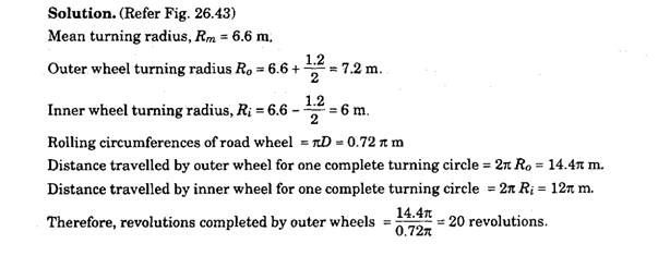
Differential When both rear wheels are connected to a common driving shaft rapid wear of\rear tyre, and difficulty in steering from the straight-ahead position are soon experienced. It can be seen in Fig. 26.43 that the outer wheel must travel a greater distance than the inner wheels during cornering of the vehicle. Hence, if the wheels are interconnected, the tyres have to 'scrub' over the road surface and tend to keep the vehicle moving straight ahead. These problems can be minimized by driving one wheel and allowing the other to run free. But this provides unbalanced driving thrust and unequal cornering speeds due to which the arrangement was not accepted. The problem was solved in 1827 by Pequeur of France who invented the differential. This mechanism rotates the wheels at different speeds, while maintaining a drive to both wheels. Example 26.4. The steering set of a, vehicle provides a turning-circle radius of 6.6 m with a wheel-track width of 1.2 m. The effective road whe

Bearing Loads

Image
:: Bearing Loads :: Bearing loads due to side thrust on a wheel in semi-floating axle is shown in Fig. 26.55. Let F = lateral force at the rim of the wheel r = radius of the wheel L = distance between the centres of wheel bearings R1 and R2 = radial reactions of the wheel bearing on the wheel hub P = the thrust reaction of the bearing In practice, the radio rIL ~ 0.6. Considering the forces in the horizontal and vertical directions, P = F and R\=R2 Fig. 26.55. Bearing loads due to side thrust on semi-floating axle. Therefore, for semi-floating type axles, P is equal to F, and Ri and R2 each approximately equal to three fifth ofF.Ri adds to the normal static load on the bearing, whereas R2 opposes it. Axle Shaft Shafts for semi-floating type axles are subjected to both bending and torsion. Hence, the diameter, of the shaft should vary with the bending moment along the length. Accordingly, the diameter is minimum near the differential e

Rear Axle [Automobile]

Image
Rear Axle [Automobile] The vehicle with non-independent rear suspension uses either a dead axle or a live axle. The dead axle only supports the weight of the vehicle, but the live axle besides fulfilling this task, contains a gear and shaft mechanism to drive the road wheels. The arrangements for supporting the road-wheels on live axles and providing the driving traction use an axle-hub mounted on to the axle-casing and supported by ball or roller-bearing. The two main components installed inside the axle of a rear-wheel drive vehicle are the final drive and differential. 26.6.1. Axle Casing The casing used now a days is either a banjo or carrier-type. In the past a split (trumpet) casing was occasionally used. These three types are shown in Fig. 26.51. The type of axle casing used decides the method for the removal of the final drive. Banjo Type The tubular axle section of this casing is built up of steel pressings, which is welded together and suitably strengthened to withstand the

Front Wheel Drive

Image
Front Wheel Drive In front wheel drive both the engine and transmission system are assembled in one unit, which is mounted at the front of the vehicle. This arrangement provides the following ad­vantages. (i) Compact construction is obtained. (ii) Flat floor of passenger compartment is possible in absence of propeller shaft tunnel or gearbox bulge. (iii) Good traction is provided as majority of weight is taken by the driving wheels.  (iv) Engine can be mounted transversely so that either bonnet length is reduced or the size of the passenger compartment is increased. (v) Good steering stability is exhibited as driving thrust of the wheels is aimed in the direction that the vehicle is intended to follow. Also the layout rarely suffers from the oversteer characteristics. The front wheel drive vehicles require more complicated drive shafts, but in view of the many advantages the layout is very suitable for small cars. In the typical front wheel drive layout shown in Fig. 26.59, the transv

Four Wheel Drive

Image
Four Wheel Drive (Automobile) The two main traction problems associated with a two-wheel drive (4 x 2) vehicle are loss of traction during cross-country operation and loss of adhesion during acceleration. To provide a solution to these problems, Harry Ferguson, the inventor of the light weight tractor, was the first person to understand the importance of "all-wheel drive". In 1954 he patented the "Ferguson Formula" (FF), which was used on the Jensen car in the early 1960s. In a four-wheel drive (4 x 4) vehicle (four by four vehicles), the drive is transmitted to all the four wheels. The intended use of the vehicle governs the type of 4 x 4 drive system that is offered by the manufactures. Some vehicles are designed to work efficiently both on and off the highway. These vehicles use two-wheel drive on 'hard' surfaces and restrict the use of four-wheel drive for cross-country operation where it is likely to encounter muddy surfaces leading to loss of traction

Bearing Lubrication

Image
Bearing Lubrication The whole hub assembly is partially packed with grease. A radial-lip grease-seal is pressed inside the hub next to the larger bearing. The lip of the seal faces this bearing and fits over the cylindrically machined surface on the stub-axle. Over packing bearing hubs with grease causes churning and develops very high running temperatures. Due to high temperatures and excessive mechanical working the grease breaks down and becomes soft. The centrifugal force acting on the grease in the hub pushes soft grease outwards, so that it flows towards the lip seal and seeps past the seal lips. Bearing greases are based on mineral oil and to thicken the oil soaps of calcium, sodium, or lithium compounds are added. The consistency of a grease depends on the viscosity of the base oil as well as on the structure and properties of the metallic soap added. The three most important properties of a grease includes : (i) the melting temperature, at which the grease loses its semi-soli