Posts

Showing posts with the label F

Four-link (Semi-Hotchkiss) Drive

Image
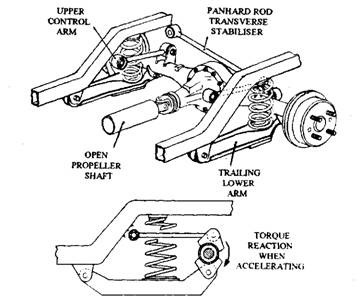
Four-link (Semi-Hotchkiss) Drive When helical springs are used in conjunction with a live rear axle, these springs cannot take driving and braking thrust, torque reaction or give lateral support to the rear axle. Therefore additional arrangements must be incorporated to meet these requirements. It may appear that the helical spring provides a reduction in the unsprung weight, but in practice when the weight of the additional locating arms and rods fitted to support this arrangement is added, the unsprung weight difference becomes very small. However, this layout allows for an accurate positioning of the axle which is an advantage. The rear axles is positioned by upper and lower trailing suspension arms in the four-link drive system layout as illustrated in Fig. 26.29.  These arms transmit driving thrust and prevent rotation of the axle casing. A transverse stabilizer, called a Panhard rod, connects the rear axle to the vehicle body and thereby controls sideways movement of the axle.

Front Wheel Drive

Image
Front Wheel Drive In front wheel drive both the engine and transmission system are assembled in one unit, which is mounted at the front of the vehicle. This arrangement provides the following ad­vantages. (i) Compact construction is obtained. (ii) Flat floor of passenger compartment is possible in absence of propeller shaft tunnel or gearbox bulge. (iii) Good traction is provided as majority of weight is taken by the driving wheels.  (iv) Engine can be mounted transversely so that either bonnet length is reduced or the size of the passenger compartment is increased. (v) Good steering stability is exhibited as driving thrust of the wheels is aimed in the direction that the vehicle is intended to follow. Also the layout rarely suffers from the oversteer characteristics. The front wheel drive vehicles require more complicated drive shafts, but in view of the many advantages the layout is very suitable for small cars. In the typical front wheel drive layout shown in Fig. 26.59, the transv

Four Wheel Drive

Image
Four Wheel Drive (Automobile) The two main traction problems associated with a two-wheel drive (4 x 2) vehicle are loss of traction during cross-country operation and loss of adhesion during acceleration. To provide a solution to these problems, Harry Ferguson, the inventor of the light weight tractor, was the first person to understand the importance of "all-wheel drive". In 1954 he patented the "Ferguson Formula" (FF), which was used on the Jensen car in the early 1960s. In a four-wheel drive (4 x 4) vehicle (four by four vehicles), the drive is transmitted to all the four wheels. The intended use of the vehicle governs the type of 4 x 4 drive system that is offered by the manufactures. Some vehicles are designed to work efficiently both on and off the highway. These vehicles use two-wheel drive on 'hard' surfaces and restrict the use of four-wheel drive for cross-country operation where it is likely to encounter muddy surfaces leading to loss of traction

Front Axle and Steering System

Image
Front Axle and Steering System Front axle carries the weight of the front part of the automobile as well as facilitates steering and absorbs shocks due to road surface variations. The front axles are generally dead axles, but are live axles in small cars of compact designs and also in case of four-wheel drive. The steering system converts the rotary motion of the driver's steering wheel into the angular turning of the front wheels as well as to multiply the driver's effort with leverage or mechanical advantage for turning the wheels. The steering system, in addition to directing the vehicle in a particular direction must be arranged geometrically in such a way so that the wheels undergo true rolling motion without slipping or scuffing. Moreover, the steering must be light and stable with a certain degree of self-adjusting ability. Steering systems may also be power assisted. The chapter discusses the front axle construction and its align­ment, and steering geometry and steering

Front-wheel Toe-in or Toe-out

Image
Front-wheel Toe-in or Toe-out Toe-in is the amount by which the front-wheel rims are set closer together at the front than at the rear with the wheels in straight ahead position when the vehicle is stationery (Fig. 26.16A). Alternatively, toe-out is the amount by which the front-wheels rims are set farther apart at the front than at the rear (Fig. 27.16B). Therefore in Fig. 27.16, toe-in =Tr-Tf and toe-out = Tf-Tr. Fig. 27.16. Steering toe-in and toe-out. Toe-in or toe-out compensates for movement within steering ball-joints, suspension rubber bush-joints, and any slight deflection of the track-rod arms or suspension arms when the vehicle is in motion. The objective of the non-parallel stationary alignment of the front steered wheels is for the toe-in or toe-out to be taken up when the vehicle is moving, so that both wheels run parallel under normal driving conditions. Toe-in neutralises the cone rolling effect of front wheels caused by camber angle. The amount of toe-in for any vehic

Front Wheels Alignment

Image
Front Wheels Alignment 27.2.1. Need for Front Wheel Alignment For free movement of the road-wheels with the least of effort, opposite wheels must be approximately parallel to each other when the vehicle is in motion along a straight path (Fig. 27.8). Each wheel has a tendency to negotiate a path perpendicular to its own axis of rotation. Therefore, if the front wheels are aligned for converging towards the front, then during movement in the forward direction both wheels try to roll close together. On the other hand, if the wheels are aligned for diverging towards the front, the wheels try to roll farther apart. Therefore due to free rolling tendency the average path followed by both wheels have a continuous tendency to either push together or pull apart. Consequently, while rolling forward, each wheel simultaneously tends to slip laterally, so a continuous cross tread scrub action is established, resulting in excessive tread wear, heavy steering and probably leading to poor fuel consum

Flywheel

Image
Flywheel A flywheel is a heavy wheel, where energy is stored as momentum. In cars, the flywheel sits between the engine and the transmission. It spins, storing energy from the engine. When the transmission engages the flywheel, that energy is transferred.

four-bar linkage

Image
A four-bar linkage [or] simply a 4-bar or four-bar is the simplest movable linkage . It consists of four rigid bodies (called bars or links), each attached to two others by single joints or pivots to form a closed loop. Four-bars are simple mechanisms common in mechanical engineering machine design and fall under the study of kinematics . If each joint has one rotational degree of freedom (i.e., it is a pivot), then the mechanism is usually planar , and the 4-bar is determinate if the positions of any two bodies are known (although there may be two solutions). One body typically does not move (called the ground link , fixed link , or the frame ), so the position of only one other body is needed to find all positions. The two links connected to the ground link are called grounded links . The remaining link, not directly connected to the ground link, is called the coupler link . In terms of mechanical action, one of the grounded links is selected to be the input link , i.e., th

leevenspark: Diesel: The Fuel of the Future?

leevenspark: Diesel: The Fuel of the Future?

Fuel and Lubrication

Image
Fuel and Lubrication The only fuel used for automobile operation is specially formulated gasoline, even though diesel fuels are used for many trucks and buses and a few automobiles. The things in a good fuel for automobile are proper volatility, sufficient antiknock quality, and freedom from polluting by-products of combustion.                                                                                                                              The volatility is reformulated seasonally by refiners so that sufficient gasoline vaporizes, even in extreme cold weather, to permit easy engine starting. Antiknock compounds, principally tetraethyl lead, were added to most gasolines to prevent knocking, a rapid, uncontrolled burning in the final stages of combustion that results in a characteristic "knock," or pinging noise, and may damage an engine or reduce its performance. Small lead deposits on such places as engine-valve seats improve valve life. Antiknock quality is rated

FOUR STROKE INTERNAL COMBUSTION ENGINE

Image
FOUR STROKE INTERNAL COMBUSTION ENGINE This is an animated computer drawing of one cylinder of the Wright brothers' 1903 aircraft engine. This engine powered the first, heavier than air, self-propelled, manoeuvrable, piloted aircraft; the Wright 1903 Flyer. The engine consisted of four cylinders like the one shown above, with each piston connected to a common crankshaft . The crankshaft was connected to two counter-rotating propellers which produced the thrust necessary to overcome the drag of the aircraft. The brothers' design is very simple by today's standards, so it is a good engine for students to study to learn the fundamentals of engine operation. This type of internal combustion engine is called a four-stroke engine because there are four movements, or strokes , of the piston before the entire engine firing sequence is repeated. The four strokes are described below with some still figures. In the animation and in all the figures, we have colored the fuel/air i