Posts

Showing posts with the label Worm and Wheel Drive

Crown Wheel Adjustment

Image
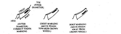
Crown Wheel Adjustment After setting the pinion, the crown wheel is installed in the assembly. The correct bearing cap must be used during this operation, as these are not interchangeable. Backlash is adjusted at this stage by moving the crown wheel towards or away from the pinion. Prior to the final measurement of backlash with a clock gauge, it is necessary to ensure that the crown wheel run-out is within the recommended limits. Meshing of the gear is checked by applying a smear of marking compound to the driving side of a few crown wheel teeth and then turning the pinion in the direction of rotation while applying a resistance to the crown wheel. The marking thus obtained indicates the mesh of the gears with respect to pinion position and backlash. Figure 26.41 illustrates the change, in relation to the correct marking, when the pinion position is changed.  A 'correct' marking indicates only a limited contact between the teeth under light-load test conditions. But if full lo

Pinion Adjustment

Image
Pinion Adjustment The pinion bearing preload adjustment depends on the type of spacer used to hold the bearings apart. Two main arrangements using a rigid spacer and a collapsible spacer are illustrated in Fig. 26.40. A bearing arrangement with a rigid spacer has a series of shims to control the static load on the bearings (Fig. 26.40A). On this arrangement the pinion nut is fully tightened before the preload is measured and shims are either added or removed if found incorrect. With this typeof spacer, the renewing of the pinion oil seal is simplified, because the seal replacement does not alter bearing preload provided the pinion nut is fully tightened Fig. 26.40. Pinion bearing adjustment The use of a collapsible spacer (Fig. 26.40B) saves time on the preload operation. While holding the bearings in alignment, this ductile steel spacer collapses under-pressure from the pinion nut so that the preload can be set in one operation. With the pinion, bearings and seal in position, the nut

Preloading of Bearing

Image
Preloading of Bearing To support both the crown wheel and pinion, adjustable taper roller bearings are normally used in a final drive assembly. If each bearing is adjusted for a small clearance between the rollers and tracks, end-float and misalignment of the gear result. This causes gear noise and premature bearing failure, because of incorrect meshing and uneven loading respectively. Even if the clearance is removed, similar effects are produced due to the elasticity of the bearing material unless this is also taken into account. To overcome these problems, all adjustable bearings employed for final drives are preloaded by forcing them together to the position they occupy when the unit is under full load. Preloading is carried out through the means provided for the adjustment. In the case of pinion bearings the extent of this pre-compression is indicated by the torque required to rotate the pinion in its housing. The recommended preload normally states the conditions under which it i

Bevel-drive Adjustment

Bevel-drive Adjustment Currently used bevel drive operates under severe conditions, but extends satisfactory service provided correct adjustment of the gear is made. Every manufacturer provides detailed specifications of special tools to be used, clearances to be maintained, etc. It is necessary to strictly follow this information before attempting such an overhaul. The final drive produces noise due to the bearing defects or incorrect meshing, which may be caused by bearing wear. Usually noise or 'whine' on the drive is produced due to the gear with too deep in mesh, and noise on the over-run is caused by insufficient depth of mesh. The cause for a final-drive noise should be determined soon whenever it develops. Misaligned gears 'mate' to the new position, so it becomes impossible to obtain a quiet operation even when the adjustment is corrected. A delay in repair may require the installation of a new crown wheel and pinion as well as bearing.

Worm and Wheel Drive

Image
Worm and Wheel Drive Since this drive is expensive, it is rarely used nowadays as a final drive on light vehicles, but is still used on heavy vehicles. However, this type of gear has a number of other applications on motor vehicles. Various arrangements, illustrated in Fig. 26.38, can be employed to provide a very quiet and long-lasting gear, but efficiency is less than the bevel (94 percent against 98 percent). This type of gear provides a large reduction in a small space. The worm may be mounted below (under-slung) or above (overhead) the wheel. An hour-glass or Hindley worm embraces more teeth than the straight worm but adjustment becomes more critical. Fig. 26.38. Worm drives. The sliding action of the worm causes friction, which is reduced by using a worm wheel of phosphor-bronze and a worm of case-hardened steel, but still the unit becomes hot. A large, well-cooled sump is incorporated to reduce oxidation of the oil at high temperature, which otherwise causes the oil to thicken.