Posts

Bearing Loads on the Front Axle

Image
Bearing Loads on the Front Axle Figure 27.6 illustrates the forces and the reactions on steering knuckle when the vehicle is at rest. The thrust load and the knuckle-pin-bearing load can be expressed in terms of the reaction of wheel on wheel spindle. Let, Rw = The reaction of the wheel on the spindle acting vertically through the centre of contact of tyre on ground.  Rt = The load on the thrust bearing Ru = The load on the upper knucklepin bearing  Rl = The load on lower knucklepin 'B' and 'C represent the centres of lower and upper knuckle-pin bearings respectively.  'A' is a point on the spindle axis in the centre plane of the wheel. Fig. 27.6. Forces and reaction on steering knuckle. The other loads acting on knuckle-pin bearing are those due to the rolling resistance and road shocks. These loads are proportional to the static load and hence can be accounted for.

Types of Front Hub Assembly

Image
Types of Front Hub Assembly The stub axle construction depends on whether it is a driving or non-driving hub. Non-driving Hub Figure 27.4A illustrates a typical bearing arrangement for a non-driving hub. This consists of a stub-axle, an externally cylindrical sleeve hub, a pair of taper-roller bearings, a grease-seal, a castellated adjustment nut and split-pin, a washer, and a dust-cap (Fig. 27.7). A centrally flanged cylindrical sleeve hub is fitted over small outer and large inner taper-roller bearings, which are supported on the stub axle. The hub is made of malleable iron or steel cast. The bearings are designed to absorb both radial and axial loads when assembled. The slackness between the taper rollers and the inner and outer races are taken up by spinning the hub assembly while at the same time tightening the adjustment nut until all the free lay has been taken up. The bearings are then preloaded by tightening the nut with a torque wrench to some predetermined torque setting. T

Front Axle and Steering System

Image
Front Axle and Steering System Front axle carries the weight of the front part of the automobile as well as facilitates steering and absorbs shocks due to road surface variations. The front axles are generally dead axles, but are live axles in small cars of compact designs and also in case of four-wheel drive. The steering system converts the rotary motion of the driver's steering wheel into the angular turning of the front wheels as well as to multiply the driver's effort with leverage or mechanical advantage for turning the wheels. The steering system, in addition to directing the vehicle in a particular direction must be arranged geometrically in such a way so that the wheels undergo true rolling motion without slipping or scuffing. Moreover, the steering must be light and stable with a certain degree of self-adjusting ability. Steering systems may also be power assisted. The chapter discusses the front axle construction and its align­ment, and steering geometry and steering

Wheel Alignment Checking and Adjustment

Image
Wheel Alignment Checking and Adjustment The alignment for suspension and steering linkage is usually checked and adjusted if, GO abnormal tyre were exists, (ii) the automobile handling is felt improper, (Hi) the suspension has been repaired, or (iv) a normal preventive maintenance check becomes necessary. In the past the wheel alignment was measured using a trammel gauge, but nowadays either an optical or an electronic gauge is used. Before tracking the wheels, the following preliminaries should be undertaken. (a) The tyre pressures are checked. (b) The correct load on the vehicle is ensured. (c) The wheels are positioned in the straight ahead position. (d) The vehicle is moved forward to settle the steering. (e) The run-out (buckle) of the wheel in checked and the maximum run-out is positioned so that it does not affect the alignment measurement. Prior to aligning the front suspension and steering systems, the factors to be ascertained that the suspension pivots and ball joints are i

Front-wheel Toe-in or Toe-out

Image
Front-wheel Toe-in or Toe-out Toe-in is the amount by which the front-wheel rims are set closer together at the front than at the rear with the wheels in straight ahead position when the vehicle is stationery (Fig. 26.16A). Alternatively, toe-out is the amount by which the front-wheels rims are set farther apart at the front than at the rear (Fig. 27.16B). Therefore in Fig. 27.16, toe-in =Tr-Tf and toe-out = Tf-Tr. Fig. 27.16. Steering toe-in and toe-out. Toe-in or toe-out compensates for movement within steering ball-joints, suspension rubber bush-joints, and any slight deflection of the track-rod arms or suspension arms when the vehicle is in motion. The objective of the non-parallel stationary alignment of the front steered wheels is for the toe-in or toe-out to be taken up when the vehicle is moving, so that both wheels run parallel under normal driving conditions. Toe-in neutralises the cone rolling effect of front wheels caused by camber angle. The amount of toe-in for any vehic

Castor

Image
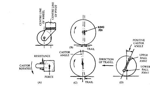
Castor Caster angle is the tilt of the king pin or ball joint centre line from the vertical towards either the front (negative caster) or rear (positive caster) of the vehicle (Fig. 27.15). The weight of automobile having positive castor tends to turn a wheel inward to allow the body to lower. Negative castor causes an outward turning effect. Wheel castor enables the driver to feel the straight ahead position so that he may steer in a straight path.     During cornering, a torque must be exerted on the steering wheel to overcome the self centring or castor action, which tends to keep the wheels pointing straight ahead. The castor angle produces a trailing effect and hence gives the directional stability. Incorrect castor can produce difficulties like hand steering, pulling to one side when brakes are applied and shimmy. To understand the action of this steering feature, the operation of a simple furniture castor (Fig. 27.15A) fitted to a trolley may be considered. Force acting on the t

Front Wheels Alignment

Image
Front Wheels Alignment 27.2.1. Need for Front Wheel Alignment For free movement of the road-wheels with the least of effort, opposite wheels must be approximately parallel to each other when the vehicle is in motion along a straight path (Fig. 27.8). Each wheel has a tendency to negotiate a path perpendicular to its own axis of rotation. Therefore, if the front wheels are aligned for converging towards the front, then during movement in the forward direction both wheels try to roll close together. On the other hand, if the wheels are aligned for diverging towards the front, the wheels try to roll farther apart. Therefore due to free rolling tendency the average path followed by both wheels have a continuous tendency to either push together or pull apart. Consequently, while rolling forward, each wheel simultaneously tends to slip laterally, so a continuous cross tread scrub action is established, resulting in excessive tread wear, heavy steering and probably leading to poor fuel consum

Condition for True Rolling

Image
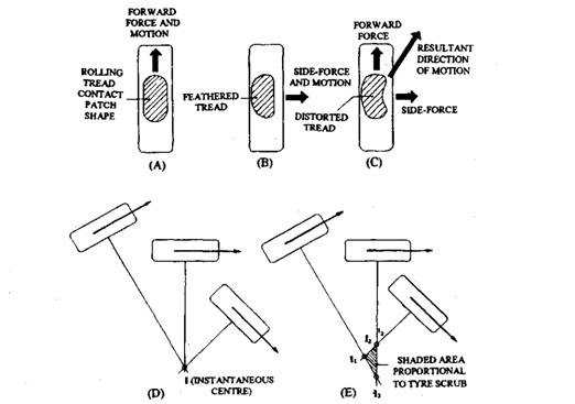
Condition for True Rolling True rolling occurs only when<the direction of motion of the vehicle is perpendicular to the wheel axis (Fig. 27.22A), i.e. the wheel is subjected to forward force. When wheel is subjected to side force that acts parallel to the wheel axis, a true scrub action is produced (Fig. 27.24B).  When the wheel is subjected to both forward and side forces, the movement is compounded of true rolling and lateral distortion (Fig. 27.22C). This condition occurs when the wheels are being steered, i.e. the direction of motion is neither parallel nor perpendicular to the axis of rotation. On a circular path, true rolling condition occurs when the projected axes of several wheels all moving in different curved paths intersect at a single point called the instantaneous centre (Fig. 27.22D). When these projected axes do not intersect at a single point, a degree of tyre scrub results (Fig. 27.22E). Fig. 27.22. Road-wheel and tyre rolling conditions.  A. True-rolling. B. True

Ackermann-linkage Geometry

Image
Ackermann-linkage Geometry In parallel-set steering arms layout (Fig. 27.26A), the track-rod dimensions yi, xi andy0, x0, remain equal for all angles of turn. With the inclined arms (Fig. 27.26B and C), the inner-wheel track-rod end dimension yi, is always smaller than the outer wheel dimension y0, while negotiating a curve. On the other hand, there is very little variation between xi and x0 for small angular movements. For small steering angles about the king-pin up to say 10 degrees, there is very little difference between yi and y0 and between the inner and outer wheel turning angles. Figure 27.26B illustrates that for a 10 degrees set track rod arms if the outer wheel is turned at 20 degrees, then the corresponding inner wheel is shown to rotate 23 degrees. Similarly for the same set, for 40 degrees outer wheel turn, the inner wheel rotates 51 degrees (Fig. 27.26 C).  Therefore, for a given angular movement of the stub axles, the inner-wheel track-rod arm and track-rod are more eff

Ackermann Linkage

Image
Ackermann Principle as Applied to Steering Ackermann Linkage The self propelled motor vehicle almost from the beginning, used the double pivot wheel steering system. This was invented for horse drawn vehicles in 1817 by George Lankensperger, a Munich carriage builder. In England, Rudolph Ackermann acted as Lankensperger's agent and a patent of the double-pivot steering arrangement was taken in his name. With this layout of the linkage the track rod arms are set parallel to each other and a track rod joins them together. In the straight ahead position of the steering, the linkage and axle beam forms a rectangle, but, as the stub-axles are rotated about their king pins, the steering arrangement forms a parallelogram. This linkage configuration turns both wheels the same amount. Figure 27.26A illustrates the parallel-set linkage positioned to provide both a 20 degrees and a 40 degrees turn for the inner and outer wheels. Charles Jeantand in 1878 introduced an improvement to the Acker

Ackermann Principle

Image
The Ackermann Principle as Applied to Steering The Ackermann Principle To achieve true rolling for a four wheeled vehicle moving on a curved track, the lines drawn through each of the four wheel axes must intersect at the instantaneous centre (Fig. 27.23). The actual position the instantaneous centre constantly changes due to the alternation of the front wheel angular positions to correct the steered vehicle's path. Since both rear wheels are fixed on the same axis but the front wheel axles are independent of each other , the instantaneous centres lies somewhere along an imaginary extended line drawn through the axis of the rear axle. The Ackermann principle is based on the two front steered wheels being pivoted at the ends of an axle-beam. The original Ackermann linkage has parallel set track-rod-arms, so that both steered wheels swivel at equal angles. Consequently, the intersecting projection lines do not meet at one point (Fig. 27.24.). If both front wheels are free to follow