Posts

Control Valve Principle

Image
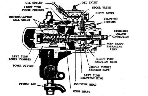
Control Valve Principle Types and Operation During operation of the engine, the fluid in power steering keeps flowing from the pump to the control valve, then back to the reservoir and both the pressure surfaces are exposed to the same system pressure. In the straight ahead position of the wheel, the fluid flows through the circuit. With the increase of steering effort, the valve shift also increases exerting proportional amount of pressure by directing fluid to one pressure surface and increasing the size of the return passage opening from the opposite pressure surface to the reservoir. Figure 27.66 illustrates the principle of operation of the control valve in neutral and during a turn. The control valve is either located inside or is attached to the exterior of the integral type power steering gear. In the link type power steering gear, the valve may be built into the end of the power cylinder or be a separate unit. The mechanical input force applied by the steering wheel on one han

Hydraulic System

Image
Hydraulic System Hydraulically operated power assisted systems work on either a constant pressure or constant flow layout. The former incorporates a hydraulic accumulator to store the pressure. The latter uses flow of fluid around the system continuously until assistance is required. The Components. The essential components required to operate a constant flow system are shown in Fig. 27.64. The system incorporates a pump, control valve and ram cylinder in addition to the normal steering components. Pump. An eccentric rotor pump driven by a vee belt from the engine crankshaft is normally used. The pump is located either on the front of the engine or at the front of the crankshaft. A fluid reservoir is attached to the pump and generally stores a low-viscosity mineral oil similar to the type used in an automatic transmission. A pressure relief valve limits the maximum pressure of 7 MN/m2, and once this pressure is attained the oil passes from the pump outlet back to the reservoir. Control

Power Assisted Steering

Image
                        Power Assisted Steering Need for Power Assisted Steering A reduction in input effort on the steering wheel rim in a manual steering system is possible by decreasing the steering box gear ratio. This increases the number of steering wheel turns from lock to lock due to which manoeuvring of the steering takes longer, and accordingly the vehicle's safe cornering speed has to be reduced. Due to the requirement of more weight on the front steering wheels of front wheel drive cars and the use of radial ply tyres with greater tyre width, larger static turning torques are necessary. Therefore, for faster driving and cornering, power assisted steering is desirable and in some cases essential if the vehicle is to be handled to match its performance. Incorporation of power assisted steering on passenger cars reduces the drivers input to about 25 - 30% of the total effort needed otherwise to manoeuvre it. In heavy trucks the hydraulic power (servo) assistance can be in

Four-wheel Steering (4WS)

Image
Four-wheel Steering (4WS) The front-to-rear wheel alignment plays a significant role in the directional stability of a vehicle. Often the lack of stability causes a dangerous drive. This is clearly observed when a car has worn suspension bushes. Up to the mid-1950s the majority of cars suffered from over-steer, mainly due to the uncontrolled movement of the rear axle caused by spring deflection which is initiated by body roll. The problems associated with an over-steer characteristic are now well understood. To improve stability, most cars nowadays are designed to exhibit under-steer characteristic when driven at high speeds. One step in obtaining an under-steer characteristic is to use body roll movement to steer the rear wheels. This is achieved either by misaligning the rear axle or by changing the geometry of the suspension system in the case of the car fitted with independent rear suspension. Although under-steer condition improves stability of the vehicle, it increases the driver

Braking of Vehicle

Image
Braking of Vehicle Figure 28.2 shows the vehicle moving down a gradient inclined at an angle, G, to the horizontal. Retardation takes place when brakes are applied. To bring the whole system in equilibrium the inertia force, which is also known as reverse effective force, is included with the system of forces actually existing. Fig. 28.2. Forces acting on a vehicle during braking while moving down on an inclined path.   Brakes may be applied (a) to the rear wheels only, (6) to the front wheels, and (c) to all the four wheels. All the three cases are discussed separately. (a) Brakes Applied to the Rear Wheels. Referring Fig. 28.2 let Fr be the braking force produced at the rear wheels. The limiting value of Fr is \lRr. The whole system is in equilibrium under the influence of coplanar forces. Therefore, 6) Brakes Applied to the Front Wheels. The Fig. 28.2 can be referred, but in this case Fr is replaced by Ff acting at the front wheels. The limiting value of Ff is n Rf- Therefore as be

Tyre Adhesion

Tyre Adhesion The amount of the force applied on a shoe against a drum controls the resistance to rotation of a road wheel. Simultaneously the road surface has to drive the wheel around. This driving force attains its limit when the resistance offered by the brake equals the maximum frictional force generated between the tyre and road which is known as the adhesive force. This force can be determined from the expression : Adhesive force = Load on wheel x Coefficient of friction When the limit is reached, the wheel starts to skid, and any extra force on the brake shoe does not increase in the rate of slowing down the vehicle, no matter how good is the braking system. This means that the adhesion between the tyre and road is the governing factor for the minimum stopping distance. Road adhesion depends on : • Type of road surface. • Conditions of surface e.g. wet, dry, icy, greasy, etc. • Designs of tire tread, composition of tread material and depth of tread. The stopping distance of a

Braking Fundamentals

Image
Braking Fundamentals Energy of Motion. Kinetic energy is the force that keeps the vehicle moving. This energy is provided by the engine in order to accelerate the vehicle from a standstill to desired speed. Kinetic energy is dissipated as heat by the brakes during application of breaks (Fig. 28.1). The kinetic energy of a vehicle during braking is given by Thus, the kinetic energy doubles as the weight doubles, but it increases four times as speed doubles. Fig. 28.1. Illustration of braking. Coefficient of Friction. Frictional force opposes the motion of the vehicle. Consequently it consumes power and produces heat. Frictional force occurs between the sliding tire and the road surface when wheel rotation is locked by brakes. The ability of a vehicle to stop depends on the coefficient of friction between the contacting surfaces. Maximum useable coefficient of friction occurs between the tyre and road surface. Passenger car brakes have coefficient of friction 0.3 to 0.5. The amount of en