Posts

Hypoid Gear

Image
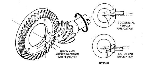
Hypoid Gear This type of gear (Fig. 26.37) is the commonly used now a days. The pinion axis of this gear is offset to the centre line of the crown wheel. Although the gear can be placed above or below the centre, but in cars it is always placed below to allow for a lower propeller shaft so that a reduction in the tunnel height is possible. Pinion offset can vary with the application, but an offset of one-fifth the wheel diametre is commonly used. If the axis is lowered, the tooth pitch of the pinion increases, so that for a given ratio, the pinion diameter can be larger (30 percent for normal offset). This enables the use of a stronger gear specifically on commercial vehicles. Fig. 26.37. Hypoid bevel. A hypoid is considered to be halfway between a normal bevel and a worm drive. In the former case a rolling action occurs, whereas the latter case is totally sliding. An increase in the sliding motion in the hypoid gear reduces meshing noise, but the high temperature and pressure of the o

Spiral Bevel

Image
Spiral Bevel Although the straight bevel is cheaper and mechanically efficient, the meshing of the gears causes an unwanted noise, which has been reduced by introducing a helical form of tooth. It is impossible to generate a helix on a tapered pinion, so the gear is called as a spiral bevel. Figure 26.36 illustrates the construction of the gear, A number of teeth are generated from the centre of the crown wheel, and form a left-handed spiral in the case of the pinion. This direction provides a large outward thrust on the drive and a smaller inward thrust on the over-run so that wear of the pinion bearing increases the backlash instead of causing seizure of the gear. Fig. 26.36. Spiral bevel. Since the crown wheel teeth are inclined to the pinion, the tooth pressures are much higher. The gear oil with no additives, and high-viscosity, suitable for the straight bevel type, is not satisfactory when used in spiral bevel units. The oil film brakes down under the high loads, causing rapid we

Straight Bevel

Image
Straight Bevel Fig. 26.35. Straight bevel The main features of the bevel type of gear is illustrated in Fig. 26.35. The tapered teeth, generated from the centre, are machined on the case-hardened steel gears and then ground together to form a 'mated pair'. The position of the crown wheel relative to the pinion determines the direction of rotation of the axle shaft. If the crown wheel is fitted on the wrong side, which is possible on some vehicles, then this provides one forward and several reverse ratios. For correct meshing and for setting the clearance between the teeth (backlash), adjusters in the form of distance pieces, shims or screwed rings are used. When backlash is too small, expansion results due to heat and wear is caused by lack of lubrication. On the other hand excessive backlash produces slackness and noise. Each manufacturer recommends a suitable backlash, but it is generally in the region of 0.15 mm for cars and 0.25 mm for heavy vehicles.

Rear Axles Final-drive

Rear Axles Final-drive The rear axles final drive (i) transmits the drive through a angle of 90 degrees, and (ii) gears down the engine revolutions to provide a 'direct top' gearbox ratio. In the case of cars a final drive ratio of approximately 4 : 1 is used. Bevel or worn gears are employed to achieve the various functions of the final drive. 26.4.1. Bevel Gears Figure 26.34 illustrates the geometry of a bevel gear layout, which represents two friction cones 'A' forming the crown wheel and 'B' the pinion. For avoidance of slippage and wear, the apex of the pinion must coincide with the centre line of the crown wheel. The system with incor­rectly positioned pinion causes unequal . peripheral speeds of the crown wheel and pinion. It is necessary to mount the gear in the correct position so that angle of the bevel is governed by the gear ratio. => Types of Bevel Gear :- 1. Straight Bevel 2. Sprial Bevel => Hypoid Gear => Worm and Wheel Drive :- 1. Bevel

de-Dion Drive

Image
de-Dion Drive The de-Dion axle is often considered as the halfway stage between the normal axle and independent suspension. This layout provides many of the advantages of the independent suspension, but the system is not classed as independent, as the rear wheels are still linked by an axle tube. In the basic arrangement illustrated in Fig. 26.33, laminated springs are mounted on the frame by a 'fixed' pivot at the front and a swinging shackle at the rear. To support the wheel on a stub axle shaft, each spring is equipped with a hub mounting, which is rigid­ly connected to a tubular axle beam. The final-drive unit, which is bolted to a cross-member of the frame, transfers the drive to road wheels through two universally jointed shafts.  The main propeller shaft is fitted with a universal joint at each end to allow for flexing of the Fig. 26.33. de-Dion drive. frame. In this design, the torque reaction of the final-drive casing is absorbed by the frame, and the driving thrust is

Torque-tube Drive

Image
Torque-tube Drive This drive system is generally used in passenger cars and light commercial vehicles. Whereas the Hochkiss drive uses stiff springs to resist torque reaction and driving thrust, the torque tube drive permits the use of either 'softer' springs or another form of spring, like helical to perform their only intended duty so that a 'softer' ride is possible. Figure 26.30 illustrates a layout using laminated springs, which are connected to the frame by a swinging shackle at each end. A tubular member called torque-tube, encloses the propeller shaft and is bolted rigidly to the axle casing. The torque-tube is positioned at the front by a ball and socket joint, which is located at the rear of the gearbox or cross-member of the frame. Bracing rods are introduced between the axle casing and the torque tube to strengthen the arrangement. A small-diameter propeller shaft is installed inside the torque tube and splined to the final-drive pinion. A universal joint is

Four-link (Semi-Hotchkiss) Drive

Image
Four-link (Semi-Hotchkiss) Drive When helical springs are used in conjunction with a live rear axle, these springs cannot take driving and braking thrust, torque reaction or give lateral support to the rear axle. Therefore additional arrangements must be incorporated to meet these requirements. It may appear that the helical spring provides a reduction in the unsprung weight, but in practice when the weight of the additional locating arms and rods fitted to support this arrangement is added, the unsprung weight difference becomes very small. However, this layout allows for an accurate positioning of the axle which is an advantage. The rear axles is positioned by upper and lower trailing suspension arms in the four-link drive system layout as illustrated in Fig. 26.29.  These arms transmit driving thrust and prevent rotation of the axle casing. A transverse stabilizer, called a Panhard rod, connects the rear axle to the vehicle body and thereby controls sideways movement of the axle.