Posts

Universal Joints (Automobile)

Image
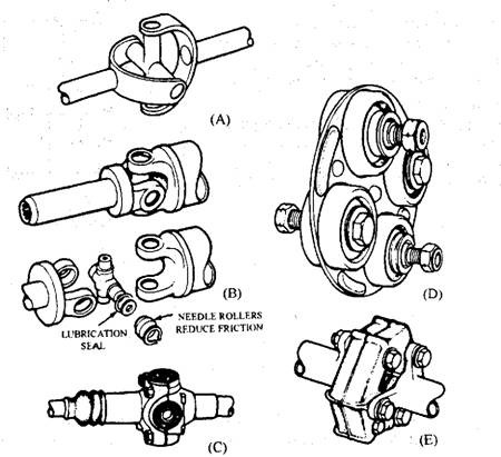
Universal Joints Universal joints are capable of transmitting torque and rotational motion from one shaft to another when their axes are inclined to each other by some angle, which may constantly vary under working conditions.  Universal joints are incorporated in the of vehicle's transmission system to perform three basic applications :  (a) Propeller shaft end joints between longitudinally front mounted gearbox and rear final drive axle.  (b) Rear axle drive shaft end joints between the sprung final drive and the unsprung rear wheel stub axle.  (c) Front axle drive shaft end joints between the sprung front mounted final drive and the unsprung front wheel steered stub axle. Universal joints have movement only in the vertical plane when they are used for lon­gitudinally mounted propeller shafts and transverse rear mounted drive shafts. When these joints have been used for front outer drive shaft they have to move in both the vertical and horizontal plane to accommodate both vertica
Image
L EEVEN S PARK a treasure of knowledge This is the site which is launched in the month of May 2009 leevenspark mainly consists of information and technical and general knowledge which is linked up with different sites which is under control by LEE VEN.you can find more important topics,situations occurs on the earth and in solar system like aeronautics.Aerospace,mechanical,Electrical and electronics.advanced Technology in industrial sectors, Mechanical,Communication and more over about the Mysterious things on the Earth took place without any of the solution,aliens. Find the all types of material,text books,drawings in PDF format through direct download please try to rise the question of the related post so we will examine and publish or the solution to your Email ID when you are subscribed to the site. OUR MAIL ID: venu.leeven@gmail.com SUPPORT THE NATURE AND BE A STEP TO   "GREEN FEATURE"

Crown Wheel Preload

Image
Crown Wheel Preload To achieve the low noise level, housing rigidity and accurate gear alignment are essential with a hypoid gear. This necessitates elimination of slackness in the crown wheel bearings by preloading. Out of the various methods used to measure the preload, the most common one is to measure the spread (outward deflection) of the bearing caps when the adjusters are screwed together. As an example, a preload cap-spread of 0.1 mm indicates that after preloading the side bearings, the distance between the bearing caps has increased by 0.1 mm.                                                                   Fig. 26.42. Final drive adjustment When shims are employed to control the backlash, the preload is obtained by increasing the shim thickness on each side of the crown wheel and the shims are added after the backlash has been set. Axles with this construction need a special tool to 'spread the caps' before the crown wheel assembly is removed or refitted. Figure 26.

Crown Wheel Adjustment

Image
Crown Wheel Adjustment After setting the pinion, the crown wheel is installed in the assembly. The correct bearing cap must be used during this operation, as these are not interchangeable. Backlash is adjusted at this stage by moving the crown wheel towards or away from the pinion. Prior to the final measurement of backlash with a clock gauge, it is necessary to ensure that the crown wheel run-out is within the recommended limits. Meshing of the gear is checked by applying a smear of marking compound to the driving side of a few crown wheel teeth and then turning the pinion in the direction of rotation while applying a resistance to the crown wheel. The marking thus obtained indicates the mesh of the gears with respect to pinion position and backlash. Figure 26.41 illustrates the change, in relation to the correct marking, when the pinion position is changed.  A 'correct' marking indicates only a limited contact between the teeth under light-load test conditions. But if full lo

Pinion Adjustment

Image
Pinion Adjustment The pinion bearing preload adjustment depends on the type of spacer used to hold the bearings apart. Two main arrangements using a rigid spacer and a collapsible spacer are illustrated in Fig. 26.40. A bearing arrangement with a rigid spacer has a series of shims to control the static load on the bearings (Fig. 26.40A). On this arrangement the pinion nut is fully tightened before the preload is measured and shims are either added or removed if found incorrect. With this typeof spacer, the renewing of the pinion oil seal is simplified, because the seal replacement does not alter bearing preload provided the pinion nut is fully tightened Fig. 26.40. Pinion bearing adjustment The use of a collapsible spacer (Fig. 26.40B) saves time on the preload operation. While holding the bearings in alignment, this ductile steel spacer collapses under-pressure from the pinion nut so that the preload can be set in one operation. With the pinion, bearings and seal in position, the nut

Preloading of Bearing

Image
Preloading of Bearing To support both the crown wheel and pinion, adjustable taper roller bearings are normally used in a final drive assembly. If each bearing is adjusted for a small clearance between the rollers and tracks, end-float and misalignment of the gear result. This causes gear noise and premature bearing failure, because of incorrect meshing and uneven loading respectively. Even if the clearance is removed, similar effects are produced due to the elasticity of the bearing material unless this is also taken into account. To overcome these problems, all adjustable bearings employed for final drives are preloaded by forcing them together to the position they occupy when the unit is under full load. Preloading is carried out through the means provided for the adjustment. In the case of pinion bearings the extent of this pre-compression is indicated by the torque required to rotate the pinion in its housing. The recommended preload normally states the conditions under which it i

Bevel-drive Adjustment

Bevel-drive Adjustment Currently used bevel drive operates under severe conditions, but extends satisfactory service provided correct adjustment of the gear is made. Every manufacturer provides detailed specifications of special tools to be used, clearances to be maintained, etc. It is necessary to strictly follow this information before attempting such an overhaul. The final drive produces noise due to the bearing defects or incorrect meshing, which may be caused by bearing wear. Usually noise or 'whine' on the drive is produced due to the gear with too deep in mesh, and noise on the over-run is caused by insufficient depth of mesh. The cause for a final-drive noise should be determined soon whenever it develops. Misaligned gears 'mate' to the new position, so it becomes impossible to obtain a quiet operation even when the adjustment is corrected. A delay in repair may require the installation of a new crown wheel and pinion as well as bearing.

Worm and Wheel Drive

Image
Worm and Wheel Drive Since this drive is expensive, it is rarely used nowadays as a final drive on light vehicles, but is still used on heavy vehicles. However, this type of gear has a number of other applications on motor vehicles. Various arrangements, illustrated in Fig. 26.38, can be employed to provide a very quiet and long-lasting gear, but efficiency is less than the bevel (94 percent against 98 percent). This type of gear provides a large reduction in a small space. The worm may be mounted below (under-slung) or above (overhead) the wheel. An hour-glass or Hindley worm embraces more teeth than the straight worm but adjustment becomes more critical. Fig. 26.38. Worm drives. The sliding action of the worm causes friction, which is reduced by using a worm wheel of phosphor-bronze and a worm of case-hardened steel, but still the unit becomes hot. A large, well-cooled sump is incorporated to reduce oxidation of the oil at high temperature, which otherwise causes the oil to thicken.

Hypoid Gear

Image
Hypoid Gear This type of gear (Fig. 26.37) is the commonly used now a days. The pinion axis of this gear is offset to the centre line of the crown wheel. Although the gear can be placed above or below the centre, but in cars it is always placed below to allow for a lower propeller shaft so that a reduction in the tunnel height is possible. Pinion offset can vary with the application, but an offset of one-fifth the wheel diametre is commonly used. If the axis is lowered, the tooth pitch of the pinion increases, so that for a given ratio, the pinion diameter can be larger (30 percent for normal offset). This enables the use of a stronger gear specifically on commercial vehicles. Fig. 26.37. Hypoid bevel. A hypoid is considered to be halfway between a normal bevel and a worm drive. In the former case a rolling action occurs, whereas the latter case is totally sliding. An increase in the sliding motion in the hypoid gear reduces meshing noise, but the high temperature and pressure of the o

Spiral Bevel

Image
Spiral Bevel Although the straight bevel is cheaper and mechanically efficient, the meshing of the gears causes an unwanted noise, which has been reduced by introducing a helical form of tooth. It is impossible to generate a helix on a tapered pinion, so the gear is called as a spiral bevel. Figure 26.36 illustrates the construction of the gear, A number of teeth are generated from the centre of the crown wheel, and form a left-handed spiral in the case of the pinion. This direction provides a large outward thrust on the drive and a smaller inward thrust on the over-run so that wear of the pinion bearing increases the backlash instead of causing seizure of the gear. Fig. 26.36. Spiral bevel. Since the crown wheel teeth are inclined to the pinion, the tooth pressures are much higher. The gear oil with no additives, and high-viscosity, suitable for the straight bevel type, is not satisfactory when used in spiral bevel units. The oil film brakes down under the high loads, causing rapid we

Straight Bevel

Image
Straight Bevel Fig. 26.35. Straight bevel The main features of the bevel type of gear is illustrated in Fig. 26.35. The tapered teeth, generated from the centre, are machined on the case-hardened steel gears and then ground together to form a 'mated pair'. The position of the crown wheel relative to the pinion determines the direction of rotation of the axle shaft. If the crown wheel is fitted on the wrong side, which is possible on some vehicles, then this provides one forward and several reverse ratios. For correct meshing and for setting the clearance between the teeth (backlash), adjusters in the form of distance pieces, shims or screwed rings are used. When backlash is too small, expansion results due to heat and wear is caused by lack of lubrication. On the other hand excessive backlash produces slackness and noise. Each manufacturer recommends a suitable backlash, but it is generally in the region of 0.15 mm for cars and 0.25 mm for heavy vehicles.