Posts

Rear Axles Final-drive

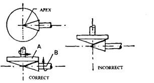
Rear Axles Final-drive The rear axles final drive (i) transmits the drive through a angle of 90 degrees, and (ii) gears down the engine revolutions to provide a 'direct top' gearbox ratio. In the case of cars a final drive ratio of approximately 4 : 1 is used. Bevel or worn gears are employed to achieve the various functions of the final drive. 26.4.1. Bevel Gears Figure 26.34 illustrates the geometry of a bevel gear layout, which represents two friction cones 'A' forming the crown wheel and 'B' the pinion. For avoidance of slippage and wear, the apex of the pinion must coincide with the centre line of the crown wheel. The system with incor­rectly positioned pinion causes unequal . peripheral speeds of the crown wheel and pinion. It is necessary to mount the gear in the correct position so that angle of the bevel is governed by the gear ratio. => Types of Bevel Gear :- 1. Straight Bevel 2. Sprial Bevel => Hypoid Gear => Worm and Wheel Drive :- 1. Bevel

de-Dion Drive

Image
de-Dion Drive The de-Dion axle is often considered as the halfway stage between the normal axle and independent suspension. This layout provides many of the advantages of the independent suspension, but the system is not classed as independent, as the rear wheels are still linked by an axle tube. In the basic arrangement illustrated in Fig. 26.33, laminated springs are mounted on the frame by a 'fixed' pivot at the front and a swinging shackle at the rear. To support the wheel on a stub axle shaft, each spring is equipped with a hub mounting, which is rigid­ly connected to a tubular axle beam. The final-drive unit, which is bolted to a cross-member of the frame, transfers the drive to road wheels through two universally jointed shafts.  The main propeller shaft is fitted with a universal joint at each end to allow for flexing of the Fig. 26.33. de-Dion drive. frame. In this design, the torque reaction of the final-drive casing is absorbed by the frame, and the driving thrust is

Torque-tube Drive

Image
Torque-tube Drive This drive system is generally used in passenger cars and light commercial vehicles. Whereas the Hochkiss drive uses stiff springs to resist torque reaction and driving thrust, the torque tube drive permits the use of either 'softer' springs or another form of spring, like helical to perform their only intended duty so that a 'softer' ride is possible. Figure 26.30 illustrates a layout using laminated springs, which are connected to the frame by a swinging shackle at each end. A tubular member called torque-tube, encloses the propeller shaft and is bolted rigidly to the axle casing. The torque-tube is positioned at the front by a ball and socket joint, which is located at the rear of the gearbox or cross-member of the frame. Bracing rods are introduced between the axle casing and the torque tube to strengthen the arrangement. A small-diameter propeller shaft is installed inside the torque tube and splined to the final-drive pinion. A universal joint is

Four-link (Semi-Hotchkiss) Drive

Image
Four-link (Semi-Hotchkiss) Drive When helical springs are used in conjunction with a live rear axle, these springs cannot take driving and braking thrust, torque reaction or give lateral support to the rear axle. Therefore additional arrangements must be incorporated to meet these requirements. It may appear that the helical spring provides a reduction in the unsprung weight, but in practice when the weight of the additional locating arms and rods fitted to support this arrangement is added, the unsprung weight difference becomes very small. However, this layout allows for an accurate positioning of the axle which is an advantage. The rear axles is positioned by upper and lower trailing suspension arms in the four-link drive system layout as illustrated in Fig. 26.29.  These arms transmit driving thrust and prevent rotation of the axle casing. A transverse stabilizer, called a Panhard rod, connects the rear axle to the vehicle body and thereby controls sideways movement of the axle.

Rear-wheel Drive Arrangements

Image
Rear-wheel Drive Arrangements The statement "every action has an equal and opposite reaction", means that every component that produces or changes a torque also exerts an equal and opposite torque tending to turn the casing. To understand the torque reaction consider the Fig. 26.25A, which represents a tractor with its rear driving wheels locked in a ditch. In this situation torque reaction is likely to lift the front of the tractor rather than turn the rear wheels. When the above principle is applied to rear axles, some arrangement must be provided to prevent the axle casing turning in the opposite direction to the driving wheels. A torque (t) applied to the wheel, which may be considered as a lever (Fig. 26.25B), produces a tractive effort (Te) at the road surface, and an equal and opposite forward force at the axle shaft. This driving thrust must be transferred from the axle casing to the frame in order to propel the vehicle. The maximum tractive effort is limited by the a

Transformers: Dark of the Moon

Image
Transformers: Dark of the Moon Director Michael Bay returns to wreak more robotic mayhem in this third entry of the Transformers franchise. Penning the further adventures of the Autobots and Decepticons is Ehren Kruger , who co-wrote the second installment. Shia LaBeouf and Tyrese Gibson topline the film, with John Malkovich and Frances McDormand heading up the supporting cast. - Jeremy Wheeler, Rovi MPAA Rating : Not Yet Rated Genre(s): Action,Science Fiction Theatrical Release Date: 06/29/2011 Status : In Theaters Distributor(s): Paramount Director(s): Michael Bay Starring: Shia LaBeouf , Tyrese Gibson , John Malkovich , Frances McDormand , Ken Jeong Themes: Robots and Androids,Evil Aliens,Metamorphosis Tone: Menacing,Slick,Tense Keywords : astronaut,battle [war],moon,robot,transformation Country of Origin: USA (zz-zz-2012),USA (07-01-2011),USA - 3D (07-01-2011),USA - IM Language : English

Rear Axles Final-drive

Image
Rear Axles Final Drive The rear axles final drive (i) transmits the drive through a angle of 90 degrees, and (ii) gears down the engine revolutions to provide a 'direct top' gearbox ratio. In the case of cars a final drive ratio of approximately 4 : 1 is used. Bevel or worn gears are employed to achieve the various functions of the final drive. 26.4.1. Bevel Gears Figure 26.34 illustrates the geometry of a bevel gear layout, which represents two friction cones 'A' forming the crown wheel and 'B' the pinion. For avoidance of slippage and wear, the apex of the pinion must coincide with the centre line of the crown wheel. The system with incor­rectly positioned pinion causes unequal . peripheral speeds of the crown wheel and pinion. It is necessary to mount the gear in the correct position so that angle of the bevel is governed by the gear ratio. Fig. 26.34. Friction cones representing bevel gear drive Types of Bevel Gear Straight Bevel The main features of the bev

Limited-Slip Differential

Image
Limited-Slip Differential A differential does not provide a high mechanical efficiency, which is desirable for the majority of mechanical components. Even if a 'low friction' differential with reduced traction over slippery surfaces is fitted, it limits acceleration of a high-power vehicle and causes excessive tyre wear. The torque reaction of the engine of such a vehicle, during acceleration, tends to lift the left-hand driving wheel off the ground. When accompanied by an uneven road surface, this causes excessive wheel spin. To minimize these drawbacks, the differential action is counteracted by artificially increasing the friction between the sun wheel and the differential cage. When this feature is included, it is called limited slip differentials. Two basic types of limited slip differential are : • Mechanical limited-slip differential  • Visco-differential Fig. 26.46. Final drive assembly with limited slip differential   Mechanical Limited-slip Differential Figure 26.46 i