Posts

Showing posts with the label R

Rzeppa Joint

Image
A Ford engineer, Alfred Hans Rzeppa (pronounced sheppa) invented one of the first practical constant velocity joints in 1926. This joint was able to transmit torque over a wide range of angles. An improved version of the joint was patented by Rzeppa in 1935.  This version uses six balls as intermediate members, which are kept at all times in a plane bisecting the angle between the input and output shafts (Fig. 26.16). A controlled guide ball cage is incorporated, which maintains the balls in the bisecting plane (or the median plane) by means of a pivoting control strut, which swivels the cage at the correct angle.  This control strut is located in the centre of the enclosed end of the outer cup member. Both ball ends of the strut are positioned in a recess and socket formed in the adjacent ends of the driving and driven members of the joint respectively. A large spherical waist approximately midway along the strut aligns with a hole made in the centre of the cage. Any angular inclinati
Obstacle avoid robot micro controlling programming

 an obstacle avoidng robot with 2 dc geared motors, a sharp ir sensor, nd nxp microcontroller p89v51rd2bn i m having problem in programmign de microcontroller . using keil i m making a hex file to burn the data into microprocessor . can u guys suggest me some programs code to make hex file i m having problem in tat #include #define forward 0x05; //0000 01 01 both motors in forward #define reverse 0x0a; //0000 10 10 both motors in reverse #define leftturn 0x06; //0000 01 10 left motor =backwards, //right motor=forward #define rightturn 0x09; //0000 10 01 left motor=forward //right motor=backwards #define obst P2 void main() { int P1,P2; P1=0xff; //intialize PORT1 as input(sensors) P2=0x00; //intialize PORT2 as output(motors) if(obst==0) //Check if sensor has detected an obstacle { P2=reverse; P2=rightturn; } else { P2=forward; //else go forward } this is my program i hav searched for but it is showing in keil tat header file cant be read ? why ? can u correct this

Worm and Wheel Drive

Image
Worm and Wheel Drive Since this drive is expensive, it is rarely used nowadays as a final drive on light vehicles, but is still used on heavy vehicles. However, this type of gear has a number of other applications on motor vehicles. Various arrangements, illustrated in Fig. 26.38, can be employed to provide a very quiet and long-lasting gear, but efficiency is less than the bevel (94 percent against 98 percent). This type of gear provides a large reduction in a small space. The worm may be mounted below (under-slung) or above (overhead) the wheel. An hour-glass or Hindley worm embraces more teeth than the straight worm but adjustment becomes more critical. Fig. 26.38. Worm drives. The sliding action of the worm causes friction, which is reduced by using a worm wheel of phosphor-bronze and a worm of case-hardened steel, but still the unit becomes hot. A large, well-cooled sump is incorporated to reduce oxidation of the oil at high temperature, which otherwise causes the oil to thicken.

Hypoid Gear

Image
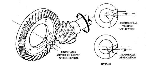
Hypoid Gear This type of gear (Fig. 26.37) is the commonly used now a days. The pinion axis of this gear is offset to the centre line of the crown wheel. Although the gear can be placed above or below the centre, but in cars it is always placed below to allow for a lower propeller shaft so that a reduction in the tunnel height is possible. Pinion offset can vary with the application, but an offset of one-fifth the wheel diametre is commonly used. If the axis is lowered, the tooth pitch of the pinion increases, so that for a given ratio, the pinion diameter can be larger (30 percent for normal offset). This enables the use of a stronger gear specifically on commercial vehicles. Fig. 26.37. Hypoid bevel. A hypoid is considered to be halfway between a normal bevel and a worm drive. In the former case a rolling action occurs, whereas the latter case is totally sliding. An increase in the sliding motion in the hypoid gear reduces meshing noise, but the high temperature and pressure of the o

Spiral Bevel

Image
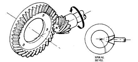
Spiral Bevel Although the straight bevel is cheaper and mechanically efficient, the meshing of the gears causes an unwanted noise, which has been reduced by introducing a helical form of tooth. It is impossible to generate a helix on a tapered pinion, so the gear is called as a spiral bevel. Figure 26.36 illustrates the construction of the gear, A number of teeth are generated from the centre of the crown wheel, and form a left-handed spiral in the case of the pinion. This direction provides a large outward thrust on the drive and a smaller inward thrust on the over-run so that wear of the pinion bearing increases the backlash instead of causing seizure of the gear. Fig. 26.36. Spiral bevel. Since the crown wheel teeth are inclined to the pinion, the tooth pressures are much higher. The gear oil with no additives, and high-viscosity, suitable for the straight bevel type, is not satisfactory when used in spiral bevel units. The oil film brakes down under the high loads, causing rapid we

Straight Bevel

Image
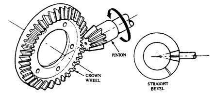
Straight Bevel Fig. 26.35. Straight bevel The main features of the bevel type of gear is illustrated in Fig. 26.35. The tapered teeth, generated from the centre, are machined on the case-hardened steel gears and then ground together to form a 'mated pair'. The position of the crown wheel relative to the pinion determines the direction of rotation of the axle shaft. If the crown wheel is fitted on the wrong side, which is possible on some vehicles, then this provides one forward and several reverse ratios. For correct meshing and for setting the clearance between the teeth (backlash), adjusters in the form of distance pieces, shims or screwed rings are used. When backlash is too small, expansion results due to heat and wear is caused by lack of lubrication. On the other hand excessive backlash produces slackness and noise. Each manufacturer recommends a suitable backlash, but it is generally in the region of 0.15 mm for cars and 0.25 mm for heavy vehicles.

Rear Axles Final-drive

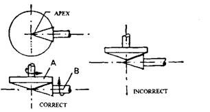
Rear Axles Final-drive The rear axles final drive (i) transmits the drive through a angle of 90 degrees, and (ii) gears down the engine revolutions to provide a 'direct top' gearbox ratio. In the case of cars a final drive ratio of approximately 4 : 1 is used. Bevel or worn gears are employed to achieve the various functions of the final drive. 26.4.1. Bevel Gears Figure 26.34 illustrates the geometry of a bevel gear layout, which represents two friction cones 'A' forming the crown wheel and 'B' the pinion. For avoidance of slippage and wear, the apex of the pinion must coincide with the centre line of the crown wheel. The system with incor­rectly positioned pinion causes unequal . peripheral speeds of the crown wheel and pinion. It is necessary to mount the gear in the correct position so that angle of the bevel is governed by the gear ratio. => Types of Bevel Gear :- 1. Straight Bevel 2. Sprial Bevel => Hypoid Gear => Worm and Wheel Drive :- 1. Bevel

Rear-wheel Drive Arrangements

Image
Rear-wheel Drive Arrangements The statement "every action has an equal and opposite reaction", means that every component that produces or changes a torque also exerts an equal and opposite torque tending to turn the casing. To understand the torque reaction consider the Fig. 26.25A, which represents a tractor with its rear driving wheels locked in a ditch. In this situation torque reaction is likely to lift the front of the tractor rather than turn the rear wheels. When the above principle is applied to rear axles, some arrangement must be provided to prevent the axle casing turning in the opposite direction to the driving wheels. A torque (t) applied to the wheel, which may be considered as a lever (Fig. 26.25B), produces a tractive effort (Te) at the road surface, and an equal and opposite forward force at the axle shaft. This driving thrust must be transferred from the axle casing to the frame in order to propel the vehicle. The maximum tractive effort is limited by the a

Rear Axles Final-drive

Image
Rear Axles Final Drive The rear axles final drive (i) transmits the drive through a angle of 90 degrees, and (ii) gears down the engine revolutions to provide a 'direct top' gearbox ratio. In the case of cars a final drive ratio of approximately 4 : 1 is used. Bevel or worn gears are employed to achieve the various functions of the final drive. 26.4.1. Bevel Gears Figure 26.34 illustrates the geometry of a bevel gear layout, which represents two friction cones 'A' forming the crown wheel and 'B' the pinion. For avoidance of slippage and wear, the apex of the pinion must coincide with the centre line of the crown wheel. The system with incor­rectly positioned pinion causes unequal . peripheral speeds of the crown wheel and pinion. It is necessary to mount the gear in the correct position so that angle of the bevel is governed by the gear ratio. Fig. 26.34. Friction cones representing bevel gear drive Types of Bevel Gear Straight Bevel The main features of the bev

Rear Axle [Automobile]

Image
Rear Axle [Automobile] The vehicle with non-independent rear suspension uses either a dead axle or a live axle. The dead axle only supports the weight of the vehicle, but the live axle besides fulfilling this task, contains a gear and shaft mechanism to drive the road wheels. The arrangements for supporting the road-wheels on live axles and providing the driving traction use an axle-hub mounted on to the axle-casing and supported by ball or roller-bearing. The two main components installed inside the axle of a rear-wheel drive vehicle are the final drive and differential. 26.6.1. Axle Casing The casing used now a days is either a banjo or carrier-type. In the past a split (trumpet) casing was occasionally used. These three types are shown in Fig. 26.51. The type of axle casing used decides the method for the removal of the final drive. Banjo Type The tubular axle section of this casing is built up of steel pressings, which is welded together and suitably strengthened to withstand the

Radial engine mechanism

Image
The radial engine is a reciprocating type internal combustion engine configuration in which the cylinders point outward from a central crankshaft like the spokes on a wheel. This configuration was very commonly used in large aircraft engines before most large aircraft started using turbine engines. In a radial engine, the pistons are connected to the crankshaft with a master-and-articulating-rod assembly. One piston, the uppermost one in the animation, has a master rod with a direct attachment to the crankshaft. The remaining pistons pin their connecting rods ' attachments to rings around the edge of the master rod. Four-stroke radials always have an odd number of cylinders per row, so that a consistent every-other- piston firing order can be maintained, providing smooth operation. This is achieved by the engine taking two revolutions of the crankshaft to complete the four strokes, (intake, compression, power, exhaust), which means the firing order is 1,3,5,2,4 and back

Robots With Their Heads in the Clouds

Image
GIST OF THE STORY : Traditionally, robots had onboard computers that controlled movements and processed data. A new approach has robots accessing processing power and data from remote servers.     In one of the many famous scenes in The Matrix (1999), the character Trinity learns to fly a helicopter by having a "pilot program" downloaded to her brain. For us humans, with our offline, nonupgradable meat brains, the possibility of acquiring new skills by connecting our heads to a computer network is still science fiction. Not so for robots. Several research groups are exploring the idea of robots that rely on cloud-computing infrastructure to access vast amounts of processing power and data. This approach, which some are calling "cloud robotics," would allow robots to off-load compute-intensive tasks like image processing and voice recognition and even download new skills instantly, Matrix-style. Imagine a robot that finds an object that it's never seen