Combined Hydraulic/Lever Rear-wheel Shoe-expander
Combined Hydraulic/Lever Rear-wheel Shoe-expander
In this case the cylinder bore (Fig. 28.42A) supports both inner and outer pistons. The outer piston uses a pressed-steel dust-cover welded to it and is grooved to carry a rectangular-cross-section rubber dust-seal. The inner piston uses a cup seal with a seal-spreader and a retainer-spring to preload the cup seal against the cylinder wall in the released position of the brakes. The tapered end of the cranked lever is housed in a triangular slot formed in each piston. This lever is located and pivoted on a pin in the body.
During application of the foot-brake, the fluid pressure pushes the inner and outer pistons until the leading shoe is forced against the drum. Consequently, the hydraulic reaction of the fluid forces the cylinder body to slide in its slot on the back in the opposite direction, until the trailing shoe is engaged against the drum. Actually, the cylinder body and pistons float between both shoes and provide an equal shoe tip load to each shoe. Since the slots in the pistons have enough clearance (Fig. 28.42B), the movement of the pistons relative to the cylinder body does not interfere with the enclosed end of the cranked lever.
During application of the hand-brake, the cable pulls the cranked-lever end away from the back-plate. This causes the lever to rotate about the pivot pin mounted in the cylinder body until its tapered end contacts the outer-piston tapered face and pushes this piston against the leading shoe. Any further pull of the cable, at this stage, gives rise to an equal and opposite reaction thrust at the pivot point. Consequently, the cylinder body slides on the back-plate away from the outer piston and hard against the trailing shoe and drum. Again, equal expanding force is applied to both shoes without causing disturbance to the inner hydraulic piston and seal (Fig. 28.42C).
 Fig. 28.42. Combined hydraulic I lever rear-wheel shoe-expander for small car.
A very similar arrangement is illuilrated in Fig. 28.43 in which the cylinder and piston both work on the foot-brake shoe-expander movement. In this system, however, a bell-crank lever engages a rectangular hole in the leading-shoe web. Application of the hand-brake pivots the lever due to which its short end forces out the leading shoe. Consequently the equal and opposite reaction acts on the pivot pin so that the cylinder body is moved in its slot in the back-plate to engage the trailing shoe.
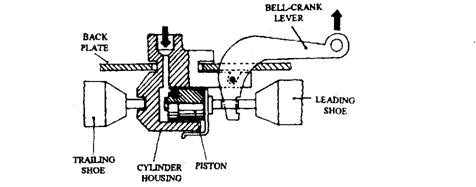 Fig. 28.43. Combined hydraulic I lever rear-wheel shoe-expander for large cars.
In this case the cylinder bore (Fig. 28.42A) supports both inner and outer pistons. The outer piston uses a pressed-steel dust-cover welded to it and is grooved to carry a rectangular-cross-section rubber dust-seal. The inner piston uses a cup seal with a seal-spreader and a retainer-spring to preload the cup seal against the cylinder wall in the released position of the brakes. The tapered end of the cranked lever is housed in a triangular slot formed in each piston. This lever is located and pivoted on a pin in the body.
During application of the foot-brake, the fluid pressure pushes the inner and outer pistons until the leading shoe is forced against the drum. Consequently, the hydraulic reaction of the fluid forces the cylinder body to slide in its slot on the back in the opposite direction, until the trailing shoe is engaged against the drum. Actually, the cylinder body and pistons float between both shoes and provide an equal shoe tip load to each shoe. Since the slots in the pistons have enough clearance (Fig. 28.42B), the movement of the pistons relative to the cylinder body does not interfere with the enclosed end of the cranked lever.
During application of the hand-brake, the cable pulls the cranked-lever end away from the back-plate. This causes the lever to rotate about the pivot pin mounted in the cylinder body until its tapered end contacts the outer-piston tapered face and pushes this piston against the leading shoe. Any further pull of the cable, at this stage, gives rise to an equal and opposite reaction thrust at the pivot point. Consequently, the cylinder body slides on the back-plate away from the outer piston and hard against the trailing shoe and drum. Again, equal expanding force is applied to both shoes without causing disturbance to the inner hydraulic piston and seal (Fig. 28.42C).
A very similar arrangement is illuilrated in Fig. 28.43 in which the cylinder and piston both work on the foot-brake shoe-expander movement. In this system, however, a bell-crank lever engages a rectangular hole in the leading-shoe web. Application of the hand-brake pivots the lever due to which its short end forces out the leading shoe. Consequently the equal and opposite reaction acts on the pivot pin so that the cylinder body is moved in its slot in the back-plate to engage the trailing shoe.


Świetnie napisany artykuł. Jak dla mnie bomba.
ReplyDelete